Invention Summary of Electric Running Board
The present invention is suitable for the technical field of automobile parts and provides an electric running pedal, which includes: a pedal, which is installed in the pedal frame and movably cooperates with the pedal frame;
The plate is used to drive the pedal to extend or retract the pedal frame; the locking mechanism is fixed on the mounting plate and is used to lock the movable shaft; and the control box is fixed on the mounting plate It is connected to the vehicle CAN wire through the connector for receiving instructions and controlling the movement of the movable shaft. The beneficial effect of the present invention is that it drives the pedal to extend or retract the pedal frame through the movable shaft for use, and when the pedal extends out of the pedal frame, due to the presence of the locking mechanism, the pedal will not retract into the pedal frame due to external force, effectively ensuring the safety of use.
The electric pedal is an auto accessory used to decorate the door sill of a car, protect the car body, and beautify the car body. It belongs to a kind of car modification products. The welcome pedal is mainly installed on the anti-mud backing plate beside the door, and it is available on all 4 doors. The shape of the car welcome pedal varies according to different models.
As a further solution of the present invention: the movable shaft is installed on the mounting plate through a drive seat and a support seat, and the free end of the movable shaft is connected with the pedal
An electric push rod is installed in the drive seat, and the output of the electric push rod is fixedly connected with the synchronization plate fixed on the movable shaft.
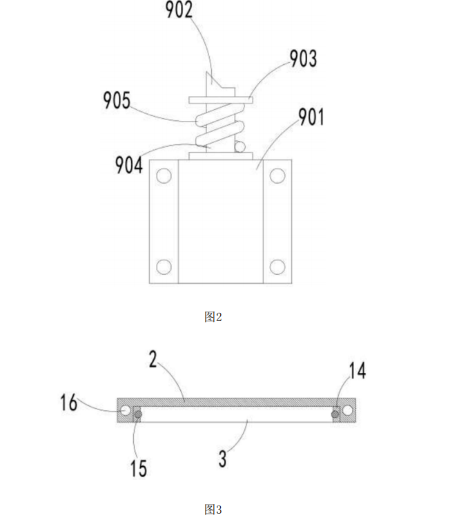
The locking mechanism includes a fixed seat, the fixed seat is movably matched with the telescopic shaft, the telescopic shaft is provided with a limit step, and the outer part of the telescopic shaft is sleeved with a spring.
Fixedly connected with the limit step, the free end of the telescopic shaft is provided with top teeth, the movable shaft is provided with a number of teeth matching the top teeth, and the movable shaft and the telescopic shaft are perpendicular to each other
The pedal frame is provided with a reminder light installation hole for installing a reminder light, and the reminder light is controlled by the control box to light up when the pedal is extended and goes out when the pedal is retracted
The pedal frame is provided with a slideway matched with the pedal, and a steel ball cage is installed in the slideway, and a plurality of steel balls are embedded in the steel ball cage, and the steel balls are in contact with the pedal
Compared with the prior art, the present invention has the beneficial effect that it drives the pedal to extend or retract the pedal frame through the movable shaft for use, and when the pedal extends out of the pedal frame, due to the lock Mechanism, the pedal will not retract into the pedal frame due to external force, which effectively guarantees the safety of use.
Note:
Figure 1 is a schematic structural diagram of an electric pedal.
Figure 2 is a schematic structural diagram of a locking mechanism in an electric pedal.
Figure 3 is a schematic diagram of the structure of a pedal frame in an electric pedal.